

Structure and working principle of multistage centrifugal pump
1. Structural composition
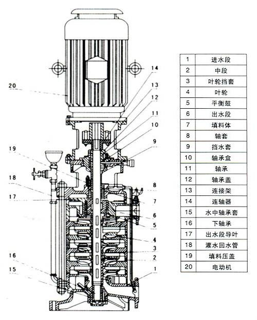
1 The multi-stage centrifugal pump is mainly composed of four parts: stator, rotor, bearing and shaft seal.
2. The rotor part is mainly composed of shaft, impeller, balance disk, shaft sleeve, etc.
3. The main components are: low-pressure suction section (feed pipe, feed chamber); pump body (volute, guide wing, anti-wear ring); high-pressure output end (pump head); balancing device (flat
Weighing pipe, balance plate, balance plate); sealing device (packing seal, mechanical seal); pump shaft (inter-shaft sleeve, impeller, positioning key, bearing) composition
4 Auxiliary devices: brackets, bases, couplings, motors, filters, etc.
2. Working principle of multi-stage pump
The liquid to be transported enters the suction port of the pump under a given pressure. Due to the action of the impeller, the kinetic energy and potential energy of the liquid increase. After the liquid enters the guide vane, part of the kinetic energy is converted into potential energy (each stage). The impeller is equipped with a guide vane), and the anti-vane of the guide vane conveys the liquid to the entrance of the next stage impeller under favorable hydraulic characteristics.
Due to the repetition of this process from one stage to the other, each stage increases the same pressure, and after passing through the final stage guide vane, the fluid enters the annular chamber of the cylindrical body and enters the discharge pipe through the discharge port.
3. Principle and function of components
1. The working principle of the balancing device
The suction port of the impeller faces the driving end of the pump. The liquid pressure on the rear cover of each stage of the impeller is greater than the liquid pressure on the front cover, and the axial force is very large, generally tens of tons to hundreds of tons. The force of tons, so the pump must have an axial force balancing device to balance the axial force of the pump rotor pointing to the suction end.
The pressure-bearing liquid from the final impeller flows into the water chamber between the balancing plate and the balancing seat through the radial gap between the balancing seat and the adjustment suite, so that the water chamber is in a high-pressure state. There is a balancing pipe behind the balancing plate connected to the inlet of the pump, and its pressure is approximately the inlet pressure of the pump. In this way, the pressure on both sides of the balancing plate is not equal, resulting in a backward axial balancing force. The magnitude of the axial balancing force changes with the change of the axial displacement, adjusting the axial gap between the balancing plate and the balancing seat (that is, changing the pressure in the water chamber between the balancing plate and the balancing seat), so as to achieve the purpose of balance. But this balance is often a dynamic balance.
2 Axial force balance
The balancing measures of the axial force of a multi-stage centrifugal pump generally include: symmetrical arrangement of the impeller, the use of a balancing drum device, a balancing disk device, and several devices such as a balancing drum and a balancing disk combination. There are also (high-pressure water pumps) using a double balancing drum mechanism. The impeller is symmetrically arranged or a balancing drum device is used, the axial force cannot be balanced, and the thrust bearing still needs to be installed to bear the residual axial force. Multi-stage centrifugal pumps are more commonly used with automatic axial adjustment
The force acting on the balancing plate to balance the axial force.
The balancing drum is a cylinder that is mounted behind the final stage impeller and rotates with the rotor. A radial gap is formed between the outer surface of the balancing drum and the pump body, with the high-pressure area of the final stage impeller at one end and the low-pressure area communicating with the suction port at the other end. The pressure difference acting on the balancing drum in this way creates a balancing force opposite to the axial force on the impeller, the magnitude of which is determined by the diameter of the balancing drum. The effect is only to reduce the axial force, but cannot balance the axial force.
3 Balance plate
The balance disc is mostly used in horizontal multi-stage pumps, which are installed after the final stage impeller and rotate with the rotor.
The balance plate generally has two functions
1. Balanced axial thrust
2. Axial positioning function
4. Pump shell
The main function of the pump shell is to seal the impeller in a certain space, so that the liquid can be sucked and pressed out by the action of the impeller. The pump shell is mostly made into a volute shape, so it is also called a volute. Due to the gradual expansion of the cross-sectional area of the flow passage, the high-speed liquid thrown out from the impeller gradually reduces the flow rate, so that part of the kinetic energy is effectively converted into static pressure energy. The pump shell not only gathers the liquid thrown out by the impeller, but is also an energy conversion device.
5 impellers
The impeller is the core part of the multi-stage pump. The blades on the large impeller with high speed and output play a major role. Before the impeller is assembled, the inner and outer surfaces of the impeller must be smooth through static balance experiments to reduce the friction loss of water flow.
6. Pump shaft
The function is to use the coupling to connect with the motor to transmit the torque of the motor to the impeller, so it is the main component to transmit mechanical energy, it not only supports all the parts on the rotor but also undertakes the role of transmitting torque
7. Bearings
The bearing is to eliminate axial movement, bear axial load and reduce end face friction. According to the different requirements of the parts, it can be divided into two forms of assembly: unit direction and two-way. During assembly, the inner diameter small ring is matched with the drive shaft, which rotates together with the drive shaft; the large inner diameter ring is installed on the support sleeve. It has a gap with the drive shaft and does not rotate together with the support sleeve. If the installation is reversed, the friction of the end face will increase, thereby losing the role of the thrust bearing.
Tel
MessageAddress: 205 National Road, Boshan Development Zone, Zibo, Shandong Province (Zhangbo Road Attached Line) Boshan Yichuan Junction
